College of Mathematical & Physical Sciences
Department of Astronomy
|
|
The Ohio State University College of Mathematical & Physical Sciences Department of Astronomy |
The LBTOSWG's specific requests to the MODS team were the following:
The camera is a modification of the one discussed at the meeting last month. The focal length was increased to 700 mm and the camera was decentered to allow an unobstructed design while imaging on to a 8K detector in the dispersion direction. The detector size in the cross-dispersion direction is 4K with 2K used for a 4 arcminute slit height. If the field is extended to 5 arc minutes in the slit direction the used area will be increased appropriately.
The results below show the diameter of the circle containing 80% of the image point spread function (D80) values in arcseconds for different slit heights as a function of wavelength with the dispersed spectrum covering the 4000 pixels .
| Slit height (arcmin) | Wavelength (nm) | ||||
|---|---|---|---|---|---|
| 564 | 530 | 499 | 460 | 434 | |
| 2 | 0.20 | 0.25 | 0.19 | 0.27 | 0.21 |
| 1.3 | 0.13 | 0.15 | 0.16 | 0.16 | 0.11 |
| 0.6 | 0.13 | 0.13 | 0.14 | 0.12 | 0.10 |
| 0 | 0.15 | 0.12 | 0.14 | 0.09 | 0.13 |
| 0.6 | 0.17 | 0.10 | 0.10 | 0.05 | 0.16 |
| 1.3 | 0.20 | 0.10 | 0.13 | 0.10 | 0.20 |
| 2 | 0.25 | 0.15 | 0.22 | 0.23 | 0.29 |
The D80 values are less than 0.3 arcseconds for all points in the spectrum. Near the center of the slit the image quality will allow narrow slits to be used if adaptive optics are used to improve the image quality through the atmosphere. The above values correspond to a resolution of R = 8000 when 4-5 pixels are binned in the dispersion direction, and double this resolution with a narrow slit with 2 pixels binned.
Overall the performance of this camera is similar to the shorter focal length camera discussed at the meeting. Furthermore, it provides a higher throughput since it is unobstructed by the detector.
| Y Displacement (arcmin) |
X Displacement (arcmin) | |||||||
|---|---|---|---|---|---|---|---|---|
| -3 | -2 | -1 | 0 | 1 | 2 | 3 | ||
| 3 | 0.69 | 0.63 | 0.48 | 0.51 | 0.49 | 0.64 | 0.91 | |
| 2 | 0.64 | 0.36 | 0.24 | 0.18 | 0.24 | 0.39 | 0.69 | |
| 1 | 0.51 | 0.24 | 0.17 | 0.15 | 0.13 | 0.27 | 0.56 | |
| 0 | 0.47 | 0.22 | 0.18 | 0.16 | 0.13 | 0.23 | 0.53 | |
| -1 | 0.54 | 0.28 | 0.19 | 0.17 | 0.15 | 0.31 | 0.60 | |
| -2 | 0.72 | 0.45 | 0.30 | 0.25 | 0.31 | 0.46 | 0.80 | |
In this mode the D80 image diameter grows to as much as 0.46 arcseconds in the corner of a 4 arcminute field and reaches a values of 0.9 arcseconds at the corner of a 5 × 6 arcminute field. The field is limited on one side by the proximity of the camera corrector to the collimated beam.
The image diameters for the different wavelength values when used in a multislit mode have not been evaluated individually. However, the values in the first table closely track the sizes and are usually less because the monochromatic images in the spectrum are not broadened by lateral color. Therefore the imaging mode D80 values give a good indication of the spectral values for a multislit mode. This assumption will be verified in future analyses.
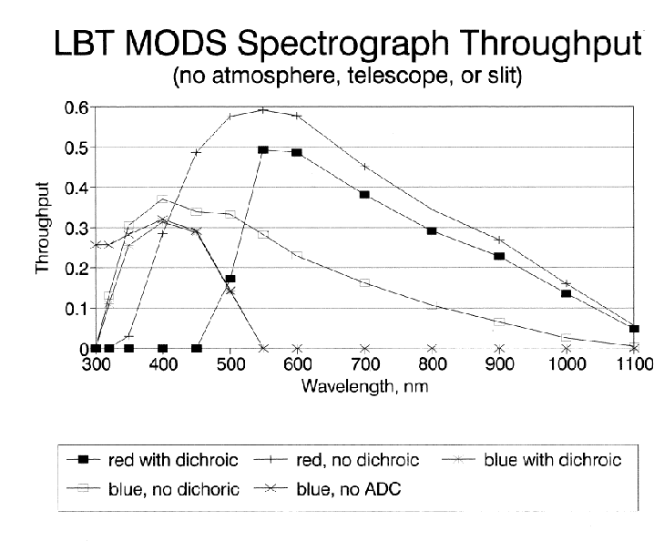
The goal of this study is to predict the throughput of the MODS spectrograph. The atmosphere, telescope and the slit are not included. All surfaces are assumed to be clean and new. In general all values are taken from actual measurements. The model for the sol-gel coatings are is the Sandia Labs base catalyzed fixed index process not the acid catalyzed graded process studied at OSU. The dichroic is assumed to be 85% efficient in both transmission and reflection which appears to be conservative. A filter is included in the red channel to block second order "blue", in many configurations this will not be required. Available designs for the ADC require glasses that would limit the throughput at the extreme blue end. Other combinations of glasses will be investigated for better throughput. The blue response is shown both with and without the ADC.

Note added 2000 Feb 14:A recalculation of the response has been done using a more efficient blue grating. You can view it here.