College of Mathematical & Physical Sciences
Department of Astronomy
|
|
The Ohio State University College of Mathematical & Physical Sciences Department of Astronomy |
Attendees: Pat Osmer, Paul Byard, Tom O'Brien, Mark Derwent, Darren DePoy, Bruce Atwood, Jen Marshall, & Rick Pogge,
Grating Tilt Prototype Tests
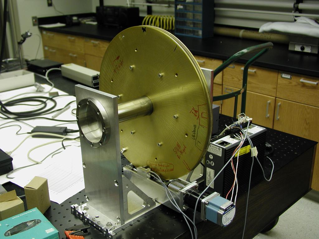
The main topic of this meeting was to hear a report by Mark Derwent on tests of the grating tilt mechanism in the mechanics lab. Clicking on the images below will load a full-resolution version.
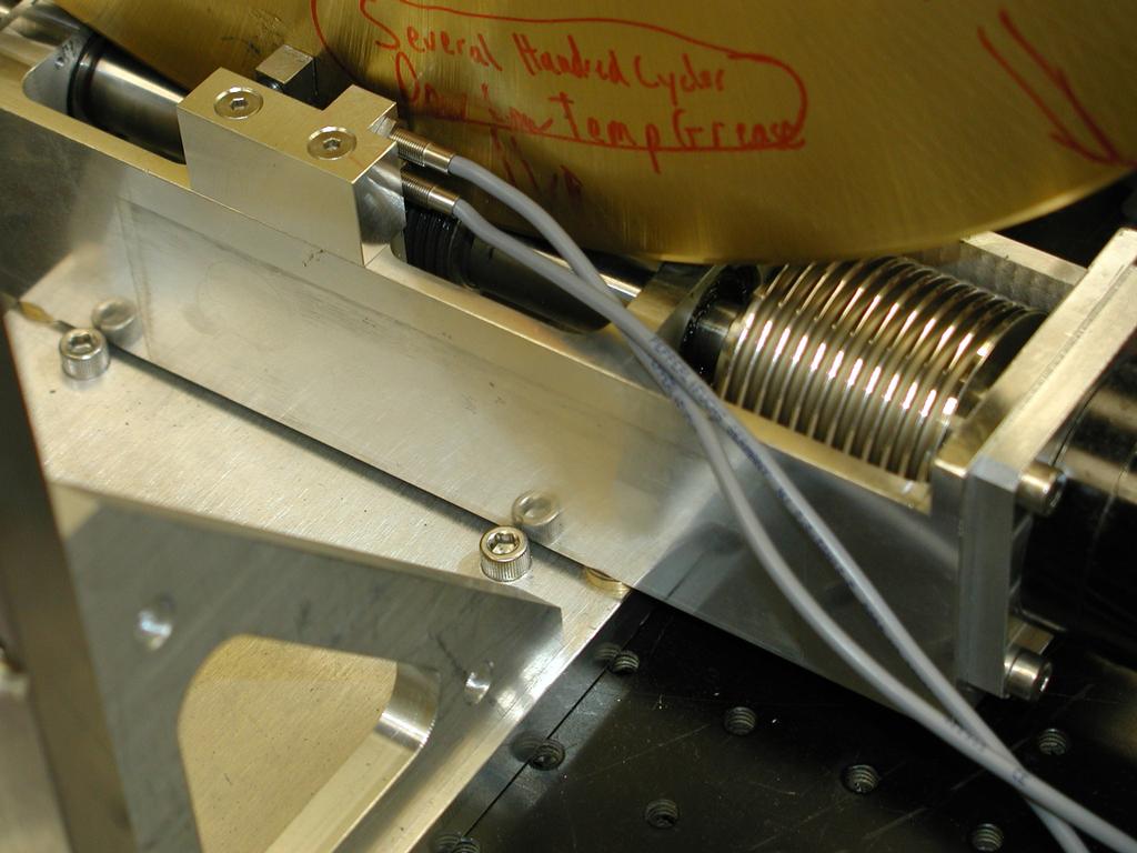
Grating drive test rig in the lab. The actual grating drives will be made by cutting the large aluminum gear in half to make drives gears for two gratings. The drive is provided by a stainless steel worm gear connected to a standard stepper motor.
For the tests, a benchtop Compumotor controller and laptop were used. An absolute encoder strip (which will not be needed for the actual drives) was used for test metrology.
The tests sought to evaluate the following properties of the grating drive system:
Grating Tilt Motion Tests
The grating tilt motion tests were setup with the following:
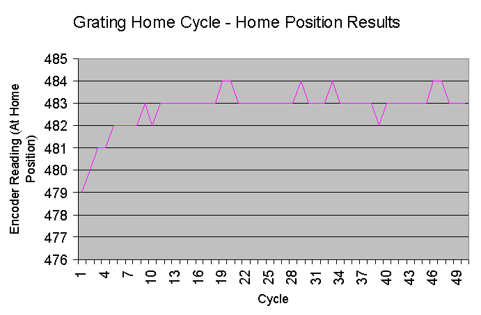
The grating home position is highly repeatable, with the home position being recovered to +/- 1 motor step. An oddity, however, is that the home position drifts after the first couple of cycles then stabilizes for all subsequent tests (up to 100 cycles). This is not understood yet.
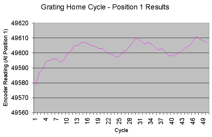
Again, the target position is highly repeatabl, her to +/- 5 encoder counts, corresponding to +/-3 arcseconds of rotation of the main gear. There are two remaining effects not understood, the slow ramp-up at the start of the cycle of tests (reflecting the home position ramp-up above), and an oscillation with a period of ~16 cycles.
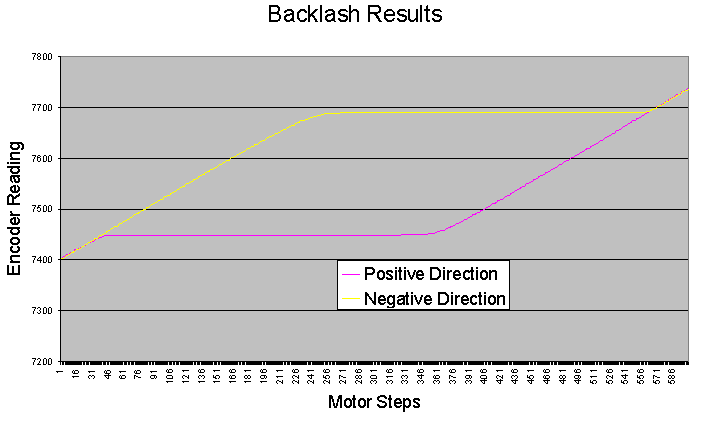
Backlash hystersis test results.
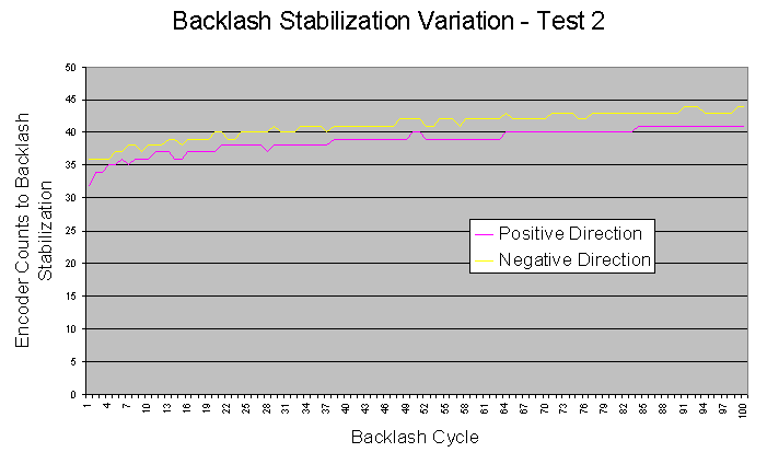
Backlash recovery repeatability results.
There was some discussion about the basis of the maintenance cycle used for the tests. If the numbers are right, it looks as if it may not be necessary over the life of the instrument, even to changing the lubricant.
Overall, the grating drive concept has passed our tests with flying colors. We will proceed to the next steps of developing the full grating drive system, and the grating mounting system.
Optics
We discussed quotes for the imaging flats, including both polishing and coating. The red channel flats will be coated with the overcoated silver, and the blue flats coated with aluminum. Prices look competive (we can't quote online...). Delivery time is 14 weeks minimum. We will also ask for witness samples of the coatings for life testing.
We received quotes for the imaging filters. After much discussion, we decided to order an SDSS filter set (5mm thickness, 86x86mm square) for the imaging filters. A complete set means the filters within that set should be parfocal.
Spectroscopic filters for order separation will need to be 182x86mm in size. We still need to determine which ones we will need, but there will be no problem obtaining standard Schott filters (e.g., GG385 and such like) in this size. This decision is coupled with the parameters of the gratings, and comes later in the project.
For the "open" position in the blue camera, a 2mm piece of polished fused Silica will permit use of MODS unfiltered (imaging or spectroscopy) without the need to refocus for the filters. No similar analysis has been done for the red camera at this time.
The next MODS meeting will be in September before the start of the Autumn quarter, but after the Labor Day holiday.
R. Pogge, 2001 August 30