College of Mathematical & Physical Sciences
Department of Astronomy
|
|
The Ohio State University College of Mathematical & Physical Sciences Department of Astronomy |
Attendees: Darren DePoy, Pat Osmer, Bruce Atwood, Dan Papallardo, Jerry Mason, Tom O'Brien, Paul Byard, Jen Marshall, Rick Pogge, Mark Derwent, Dave Steinbrecher, Ralph Belville, Ed Teiga, and Daniel DePoy.
Mechanical
Tom presented the results of his collimator system tip/tilt/focus (T/T/F) actuator repeatability tests.
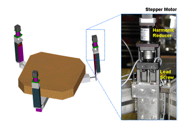
For background, the collimator support has 3 T/T/F actuators that consist of a stepper motor, a 100:1 harmonic reducer, and a linear lead screw slide. The actuator is coupled to the collimator cell support via a blade and torsion flexure in series. This flexture combination acts kinematically like a ball joint, and the combination allows the collimator mirror to move on 3 axes: focus (z-axis translation), tip (rotation about the x-axis), and tilt (rotation about the y-axis), while constraining the remaining three degrees of freedom: x- and y-axis translation and z-axis rotation (twist).

MODS Collimator Support & Actuators
(click to see larger image)
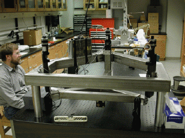
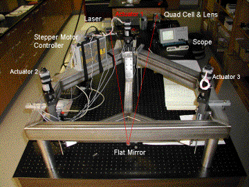
In the lab setup, the collimator support and frame were mounted on an optical bench. A mirror was attached to the frame and a laser beam bounced off the mirror and into a lens and quad-cell detector. The lens provides the same plate scale at the quad cell as would be provided by the MODS optics. One actuator was motorized while the other 2 were held fixed for the tests. The active actuator was equipped with encoder tape and a Renishaw 0.1-micron resolution encoder to provide absolute measurements.
 Actuator Test Setup |
 Light Path |
The goals of the tests were to measure three quantities:
The hysteresis loop moved the actuator 20 steps forward, measuring the position with the Renishaw at each step, then running it back 20 steps, repeating the measurements. The loop was repeated 5 times.
The loop test showed that there is adequate resolution in the actuators to make sub-pixel corrections at the MODS detectors (15-micron pixels) with no measurable motor backlash. Simply put, these harmonic reducers are really good. There was some measurable in-and-out track difference which is likely due to mechanical effects (e.g., elastic wind-up), but amounts to no more than about 0.3 microns of offset in mirror, equivalent to ~0.04 pixels on the MODS CCD. In terms of hysteresis, our actuator design performs extremely well.
[Hystersis Test Plot]
The Homing repeatability test was to run the actuator back to the low-limit position, then forward to the home position. This tests the repeatability of sensing both limit and home with the inductive proximity sensors we wish to use instead of mechanical limit switches. The home position repeatability was measured against the absolute position returned by the Renishaw encoder.
The home position repeatability is within 1-micron, with non-repeatable errors at the 0.5-micron level that we do not yet understand. They could be either hardware or software related. Otherwise 1-micron of home position repeatability is in a system with about 10cm (10,000 microns) of travel, so well within specs.
The target repeatability test was to see how well you could home the actuator then dead reckon forward to a target position. In the most thorough test performed, the target position was 1-mm (1000-microns) forward, although tests with 10-mm targets were also done with similar results. Homing and Targeting motions would be those used to move the collimator mirror to a particular absolute focus position (whereas hysteresis is critically evaluating how accurately we can move the mirror back and forth by small amounts relative to a given position to actively compensate for gravity-induced flexure).
The result was that homing and targeting motions are repeatable to about 1-micron. In a 1-mm target move, the noise envelope is about 0.8-microns rms, with the main noise source being errors in the lead screw. The additional error comes from as-yet unknown sources, and may be software related. Tom will be investigating this further.
The conclusion of the tests is that the current collimator design has passed all three tests with flying colors.
The next round of tests will seek to measure the effects of temperature on the actuator components and the proximity sensors. In particular, we will want to test how the system performs at extremes of temperature (especially extreme cold). The experiment will continue to evolve over the rest of the summer as our way to evaluate all of the components of the IMCS active control system for the collimator.
Tom's report was followed by a show-and-tell demonstration in the lab downstairs. The youngest attendee (Daniel DePoy) thought the laser sensor system was cool. There was general concensus on this.
R. Pogge, 2002 April 26