The Ohio State University
College of Mathematical & Physical Sciences
Department of Astronomy
MODS Instrument Update
2002 March 1
Click on the images for a full-resolution version.
MODS Blue Camera Optics
MODS Blue Camera design view. The Red cameras will look essentially
the same (the difference is in the optics). This view shows the
shutter, the integrated filter wheel, and part of the CCD dewar
mounting pieces (the green box is a placeholder for structures that
will be inside the CCD dewar proper). The adjustable truss design
is also visible in this view. The actual camera will be enclosed and
light-tight. [AutoCad drawing by Tom O'Brien].
MODS Camera Primary Mirror blank. This is one of four lightweight
pyrex honeycomb mirrors manufactured by Hextek Products in Tuscon, AZ.
This is a finished blank shown after slumping into the approximate
curved surface and ready for polishing. Three of the four camera
primary mirror blanks have been made and accepted. A fourth
cracked during slumping and a new blank is being made. The cracked
blank was delivered to OSU where we will use it to prototype the
camera primary cell and support system. [Photo courtesy of
Hextek].
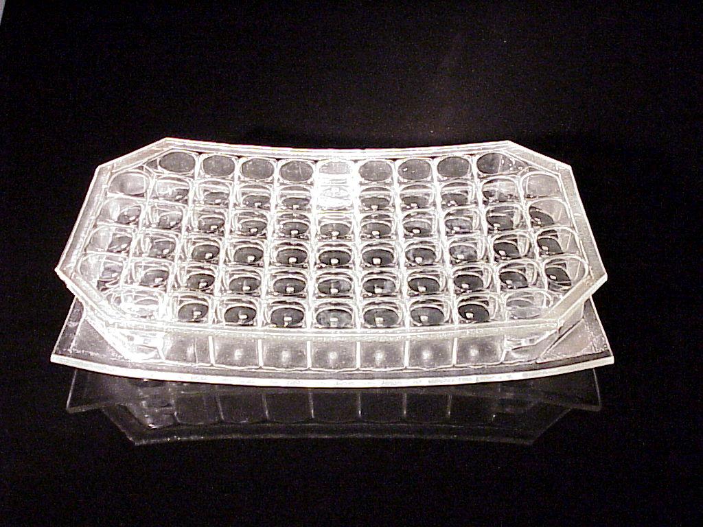
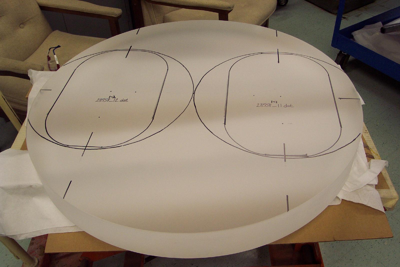
Fused-silica parent out of which the two corrector lenses for the
blue cameras (MODS1 and MODS2) will be made. The ovals show the
high-quality glass sectors in the larger parent that will become
the corrector lenses for the MODS blue cameras. It was
manufactured by Corning Glass Works in Corning, New York.
Transmission interferograms of the blank show that the glass as
formed exceeds our index homogeneity specification. It is now
sitting in the Corning plant awaiting shipping to whoever we award
the final optics contract. [Photo courtesy of Corning
Glass].
Optical raytrace of the MODS decentered Maksutov-Schmidt Cameras.
The view is along the long axis of the camera primary and corrector,
showing the basic light path (this is not an engineering diagram).
[Code-V raytracing by Paul Byard].
Engineering model of the MODS collimator mirrors and their 3-axis
active support system. The outer "diamond" frame enclosing both is
where the collimators attach to the main structure of MODS. The
blue collimator is on the left and the red collimator is on the
right. [AutoCad drawing by Tom O'Brien].
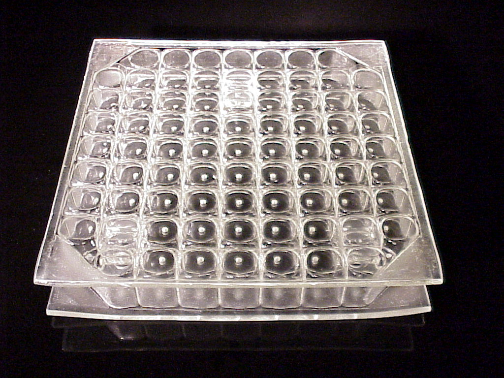
MODS Collimator Mirror blank (one of 4). Like the camera primary
mirrors, we are using lightweight pyrex honeycomb mirrors
manufactured by Hextek
Products of Tucson, AZ. The collimator mirrors are also
slumped. All 4 Hextek blanks have been accepted and will be
shipped soon to REOSC Optique in St. Pierre du Perray, France for
figuring and polishing. [Photo courtesy of Hextek.]
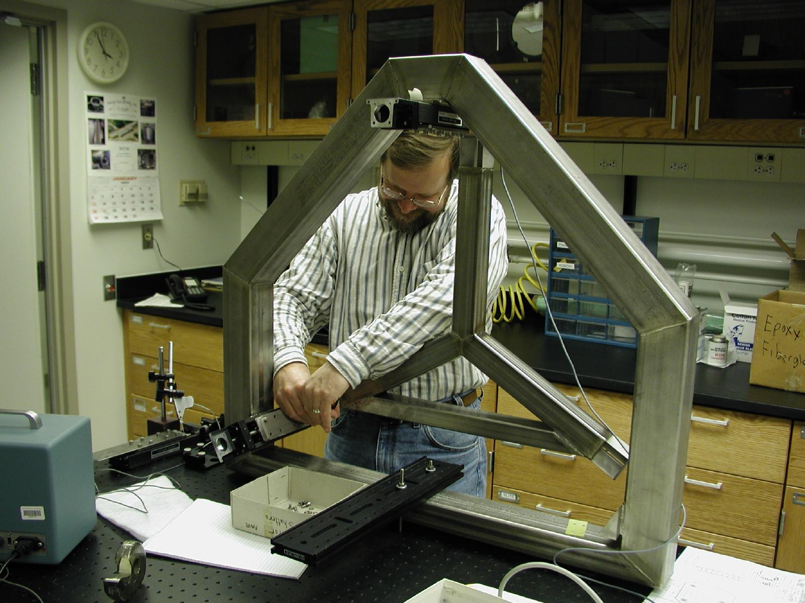
Prototype MODS collimator support frame being prepared for testing
in the OSU mechanical lab. The frame is a welded, hollow steel tube
(rectangular cross-section). Inside, the triangular structure is
the collimator mount support (which would hold the eventual
collimator cell, not yet fabricated, from behind). Tom O'Brien is
shown working on installing the three linear actuators used for
focus piston and flexure-compensation steering (tip/tilt) motions.
This prototype will be used to quantify the tip/tilt/focus
precision and repeatability of our collimator mount design.
[Photo by R. Pogge]
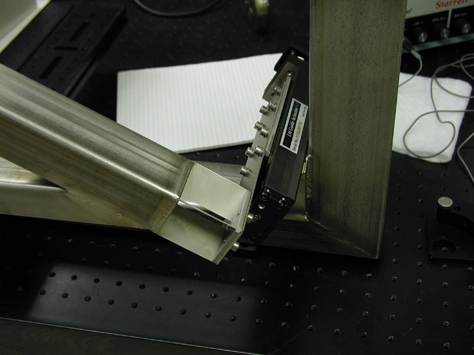
Close-up of one of the three linear actuators on the collimator
support, showing the blade and torsion flexures that connect the
actuator to the collimator frame. Harmonic reducing gears on the
actuator motors give us a linear stroke resolution of approximately
+/-0.2 microns (actual performance is being measured with this
prototype at this time). [Photo by R. Pogge]