
|
|
|
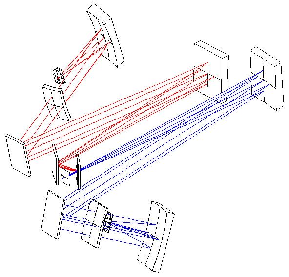
A dichroic below the slit splits incoming beam into separate red- and blue-optimized channels at a wavelength of 565nm. Each channel has separately optimized collimators, dispersers, cameras and detectors, allowing simultaneous operation across the entire wavelength region. The beam selector can also direct light into the red or blue channels alone, providing blue-/red-only modes to extend wavelength coverage into the dichroic cross-over region in one other channel.
The MODS science detectors are e2v CCD231-68 3Kx8K 15-micron pixel monolithic CCDs; blue-coated standard silicon on the blue channel and extended-red coated 40-micron deep depletion silicon on the red channel.
| Mode1 | Channel | Filter(s)2 | Resolution3 (0.6" Slit) |
Wavelength Range (nm) |
CCD Readout4 | Notes |
| Direct Imaging | Dual | B: SDSS ug R: SDSS riz |
n/a | 330-1000 | 3072x3072 | Simultaneous blue & red filter imaging with pairs of filters |
| Blue | SDSS ug | n/a | 330-700 | extended red coverage | ||
| Red | SDSS riz | n/a | 400-1050 | extended blue coverage | ||
| Grating Spectroscopy5 |
Dual | B: Clear R: GG495 |
B: 1850 R: 2300 |
320-1050 | 3088x8288 | No coverage ~560-570nm in the dichroic cross-over GG495 suppresses leaks from very blue targets |
| Blue | Clear | 1850 | 320-600 | Extended red coverage thru the dichroic cross-over | ||
| Red | GG495 | 2300 | 500-1050 | Extended blue coverage thru the dichroic cross-over | ||
| Prism Spectroscopy |
Dual | B: Clear R: GG495 |
B: 420-140 R: 500-200 |
320-1050 | 3072x4096 | No coverage ~560-570nm in the dichroic cross-over GG495 suppresses leaks from very blue targets |
| Blue | Clear | 420-140 | 320-600 | Extended red coverage thru the dichroic cross-over | ||
| Red | Clear | 500-200 | 450-1050 | Extended blue coverage thru the dichroic cross-over |
See MODS Filters for detailed specifications and transmission curves. Not all filter slots are occupied at this time, they are currently reserved for future expansion (e.g., additional grating order separation and prism band-limiting filters).
At this time we have not plans to support installation of user-provided filters.
| Channel | Position | Filter ID1 | Description | Use Notes |
| Blue | 1 | Clear | Fused Silica Clear | General Spectroscopic Mode Filter2 |
| 2 | g_sdss | SDSS g | Imaging | |
| 3 | ||||
| 4 | ||||
| 5 | UG5 | UG5+Fused Silica | Red Blocker for UV spectral flats | |
| 6 | u_sdss | SDSS u | Imaging | |
| 7 | ND1.5 | Neutral Density 1.5 | Spectral Flats and Bright Comparison Lamps | |
| 8 | ||||
| Red | 1 | Clear | BK7 Clear | General Spectroscopic Mode Filter2 |
| 2 | r_sdss | SDSS r | Imaging | |
| 3 | ||||
| 4 | i_sdss | SDSS i | Imaging | |
| 5 | GG495 | Schott GG495 | Red Grating Order Blocker | |
| 6 | z_sdss | SDSS z | Imaging | |
| 7 | ND1.5 | Neutral Density 1.5 | Spectral Flats and Bright Comparison Lamps | |
| 8 |
See MODS Gratings & Prisms for detailed specifications and resolution and blaze curves.
| Channel | Position | Grating ID1 | Description | Resolution2 (0.6" Slit) |
Wavelengths (nm) |
| Blue | 1 | Flat | Imaging Flat with Enhanced Al | n/a | 320-600 |
| 2 | G400L | 400 l/mm Blue Grating | 1850 | 320-600 | |
| 3 | P450L | FuSi+Al Double-Pass Prism | 420-1403 | 320-600 | |
| 4 | Position Empty4 | ||||
| Red | 1 | Flat | Imaging Flat with Protected Ag | n/a | 320-600 |
| 2 | G670L | 250 l/mm Red Grating | 2300 | 500-1000 | |
| 3 | P700L | TIH6+Ag Double-Pass Prism | 500-2003 | 500-1000 | |
| 4 | Position Empty4 |
| Position | Mask ID1 | Description |
| 1 | DarkMask | Dark Mask (uncut mask shell)2 |
| 2 | Imaging | 6x6-arcminute Direct-Imaging Field Stop3 |
| 3 | LS5x60x0.3 | 0.3-arcsec Segmented long-slit4 |
| 4 | LS5x60x0.6 | 0.6-arcsec Segmented long-slit |
| 5 | LS5x60x0.8 | 0.8-arcsec Segmented long-slit |
| 6 | LS5x60x1.0 | 1.0-arcsec Segmented long-slit |
| 7 | LS5x60x1.2 | 1.2-arcsec Segmented long-slit |
| 8 | LS60x5 | 60x5-arcsec spectrophotometric "fat slit" |
| 9 | SieveMask | Pinhole Sieve Mask (focus and geometric calibration) |
| Mask Material | 150um thick electroformed NiColoy®1 |
| Mask Surface Shape | Spherical (R=1040mm) |
| Mask Coating | Copper (II) Oxide (CuO) black |
| Slit Shape | Rectangular |
| Slit Lengths3 | 0.6-arcsec (360um) to 60-arcsec (36mm) |
| Slit Widths3 | 0.3-arcsec (180um) up to 10-arcsec (6mm) |
| Edge Smoothness | ~1um rms over 180mm |
| Parallelism | <1% of width in 6mm (10") for 0.3-arcsec wide slit |
| End Shapes | Square |
| Wavelength Range | 320-1100nm (Atmospheric to CCD limits) |
| Field of View | ~6.0x6.0 arcminutes (~2800x2800 pixels) |
| CCD Pixel Scale | Blue: 0.120 arcsec/pixel Red: 0.123 arcsec/pixel |
| Standard Filters | SDSS ugriz [Details] UG5 and GG495 blocking filters ND1.5 Spectroscopic Calibration |
| Throughput w/Dichroic1 | Blue: 48% at 400nm Red: 62% at 800nm |
| Throughput w/o Dichroic1 | Blue: 52% at 400nm Red: 67% at 800nm |
| Measured Image Quality (80%EE) |
|
| Nominal Wavelength range | 320-1100nm |
| Red/Blue Dichroic Cross-Over | 565nm |
| Design Slit Width | 0.6-arcsec (projects to ~4 pixels) |
| Maximum Slit Length | 6-arcmin |
| Segmented Long-Slits | 5x60x0.6, 0.8, 1.0, 1.2-arcsec |
| Dispersers | Gratings and Prisms |
| Diffraction Gratings | Red: 250 l/mm (R=2300) Blue: 400 l/mm (R=1850) |
| Double-Pass Prisms | Red: TIH6 + Ag (R=500-200) Blue: Fused Silica + Al (R=500-125) |
| Throughput w/dichroic | Blue Grating: 36% @ 400nm Red Grating: 38% @ 750nm Red Prism: 51% @ 750nm Blue Prism: 43% @ 400nm |
| Throughput w/o dichroic | Blue Grating: 39% @ 400nm Red Grating: 40% @ 750nm Red Prism: 54% @ 750nm Blue Prism: 48% @ 400nm |
| Design | Double imaging spectrograph with a dichroic beamsplitter, reflective collimators, decentered Maksutov-Schmidt cameras. |
| Focal Stations | Left and Right Direct f/15 Gregorian Foci MODS1: LDG Focus (as of September 2010) MODS2: RDG Focus (coming in 2012) |
| Field of View | 6x6-arcminute Science Field 5x6-arcminute off-center Guide Patrol Field |
| Focal Plane Scale | 1.667 arcsec/mm |
| Science CCDs | Blue: e2v CCD231-68 3072x8196 (15um pixels) Std Silicon + Astro-Broadband
coating Red: e2v CCD231-68 3072x8196 (15um pixels) 40um Deep-Depletion Silicon + Astro-ER1 coating |
| Imaging Pixel Scale | Blue: 0.120 arcsec/pixel Red: 0.123 arcsec/pixel |
| Slit Masks | 24 slot mask cassette Slit masks are laser-machined in spherical electroformed NiColloy blanks 9 mask slots reserved for standard facility slit masks 15 mask slots available for user-designed slit masks |
| Long Slit Masks | Fixed long slits (0.6, 0.8, 1.0, and 1.2-arcsec width), curved to match the focal surface |
| Multi-Slit Masks | Up to 15 user-designed masks mounted in the cassette |
| Dispersers | R=2000 Gratings R=500-100 double-pass prisms |
| Imaging | Flat mirror replaces grating, 6x6-arcmin FoV |
| Filters | 8-position filter wheels in each channel SDSS imaging and spectroscopic blocking filters |
| Collimator Focal Length | 3450mm |
| Pupil Beam Diameter | 230mm |
| Camera Design | Decentered Maksutov-Schmidt |
| Camera Focal Length | 700mm |
| Dichroic Type | Blue Transmit/Red Reflect 38-layer dielectric |
| Dichroic Cross-Over | 565nm |
| AGw Guide Camera | Steward e2v CCD57-10 512x1024 frame transfer CCD 50x50-arcsec FoV 4-position filter wheel: Clear, F525LP, Bessel-B, and ND1.0 filters |
| AGw Wavefront Sensor | Shack-Hartmann WFS Steward e2v CCD57-10 512x1024 frame-transfer CCD Potsdam 15x15 GRIN array 5x5-arcsec pickoff at the top of the guide field |
| Calibration System | Internal integrating sphere with lamps and projection optics QTH and variable-intensity incandescent flat lamps Hg, Ne, Ar, Kr, and Xe Pen-Ray wavelength calibration lamps |
| Approx Dimensions | ~4.0x2.5 meters |
| Approx Mass | 2700kg |
| Construction | Welded steel tube upper structure, welded/bolted steel-tube collimator support |
| Nominal Flexure | 500um horizon-to-zenith, uncompensated |
| Flexure Compensation | Collimator tip/tilt/focus w/closed-loop IR reference laser feedback system |
| Flexure Specification | 0.5-pixel rms motion over typical intergration (closed-loop) |