
|
|
|
This is a work in progress as we transition from commissioning to science observing. More coming soon...
At the present (2011 Nov 9), 2D Biases are not required for full-frame (8Kx3K) readout as the prescan columns remove most of the bias term without signifcant residual 2D bias structure. Imaging- (3Kx3K) and Prism- (4Kx3K) mode images still require separate bias frames until we get overscan working for subframe readout on the CCDs (a stubborn bug we haven't managed to root out yet), and it remains to be seen if subframe readout introduces significant residual 2D bias structure in the images (we suspect not, but sometimes you fix one problem and create another...).
No scripts are provided for taking dark frames.
All internal flat fields should be taken with the telescope stationary and pointed at the Zenith. They should not be taken while the telescope is moving. The instrument must be dark (closed hatch in "Calibration Mode"), and with all dome enclousure lights turned OFF. We still have some unresolved light leaks in the instrument near the mounting point with the instrument rotator that will be fixed when MODS is next off the telescope (Summer 2012), but our leak mitigation measures may not be suitable in all cases.
We have no indication that flats need to be taken "at position" on a target as the combination of the general stability of the instrument and the image motion compensation system (IMCS) obviates the need for in-place flats. Properly reduced slit flats can be used, with a small shift, to remove fringing at the far red end of the Red Channel range for very red targets, but because the fringe amplitude is at most 2% peak-to-trough, the fringe pattern is only visible in data at very high Signal-to-Noise Ratios.
The procedure that works best for grating flats is one we have adapted from the practice with the Keck LRIS instrument (link...) by taking slitless lamp flats with the grating modes. These capture enough light in the UV and far-red ends of the spectral range to work well. The blue flats use a combination of the clear and UG5 filter, the latter to suppress the red-end of the spectra in favor of more blue light (all flat-field lamps are intrinsically very red).
While we have had success taking twilight slitless flats in the red, they are not demonstrably better than internal lamp flats and are not worth the pain of chasing the twilight exposure times (better to use that time for slit illumination correction frames or twilight imaging flats). Blue twilight slitless flats, however, have too much UV in the wrong places (the sky is too blue), and there produce unacceptable pixel-to-pixel artifacts due to the annealing features on the blue CCD that become prominent at UV wavelengths. We therefore do not recommend taking slitless twilight flats in any mode.
The slitless flats are used to create normalized pixel flats: bias-subtracted frames are stacked to remove any cosmic rays, then the color term is divided out to leave just the major pixel-to-pixel variations. We then flat-field any slit flats with the pixel flat, and use that as the basis for any remaining mask-dependent calibrations (e.g., removing fringing, dichroic transmission wiggles, etc). Spectra of standard stars will also serve the same purpose (and eliminate a step).
Prism flats are tricky because of the large spectral pixels. Shows one crack at this. We use the 0.3-arcsec slit to attenuate the calibration light for long-slit mode. For MOS, you can use the stock scripts as templates but must tune the exposure times to avoid saturation. Saturation is a big issue with wider slits and we don't have a good solution yet (maybe a stronger ND filter is a future option).
The MODS Red-Channel CCD is a thick (40μm) deep-depletion device, so fringing is generally small (2-3% max peak-to-trough amplitude beyond 8500Å) compared to typical CCDs, and should not constitute a major correction for most faint targets, though it will become an issue when the signal to noise is in the high 10s in that part of the spectrum.
There are no lamp-and-filter combinations that permit simultaneous acquisition of blue and red flats, so we take them serially with the scripts below. The dichroic slightly cuts into the red end of the g filter bandpass, and there is a small change in bandpass shape for the u and r filters, so we take them explicitly for red-only and blue-only modes.
As with other flat fields, lamp flats should be taken at the Zenith with the telescope stationary.
We recommend taking wavelength calibration lamps through the 0.6-arcsec longslit mask for grating wavelength calibrations, and the 0.3-arcsec longslit mask for the prism flats. For the grating, 0.6-arcsec is the design-reference slit and you will have 80-100 reasonably bright and unblended lines to work with in the red, maybe 50 in the blue, which covers the range of interest.
Wavelength calibrations are very stable, modulo a small flexure shift of order a few pixels at most which is readily measured and removed using night sky lines (another advantage of having an 8.4m telescope). Note that because the red and blue channels are mechanically different relative to gravity below the common focal plane, any amount of shift in wavelength due to absolute instrument flexure that is not corrected for by the IMCS is expected to be different between the red and blue channels.
Only one (1) exposure per lamp or lamp combination is needed: the exposures are very short, and there are many 10s of lines, so even single CR hits are not a problem. Short exposures plus long readout times in full-frame mode mean you can waste a lot of time taking superfluous data. The MODS calibration lamp system's integrating sphere and projection optics are very efficient, and we generally have to observe the comparison lamps through strong neutral density filters (ND1.5) to avoid badly saturating the spectra.
Unlike flat fields and bias frames, it is possible to take comparison lamp spectra during the afternoon with instrument dark and full dome lights on(!), but the telescope must be at the Zenith.
The best fit RMS deviations for the grating wavelength solutions depend on the width of the slit. We found that a 0.6-arcsec long slit mask gives the best solutions. This is summarized in the table below:
| Slit Width |
Blue RMS |
Red RMS |
|---|---|---|
| 0.3 | 0.059Å | 0.010Å |
| 0.6 | 0.024Å | 0.008Å |
| 1.0 | 0.045Å | 0.018Å |
| 1.2 | 0.117Å | 0.026Å |
For the prism modes, the wavelength solutions are dominated by the strong wavelength dependence of the index of refraction of the prism glasses. The blue prism is best fit by a 4th-degree polynomial (terms to x4) whereas the red prism is best fit by a 6th-degree polynomial (terms to x6). Unlike with gratings, the prism dispersion is so nonlinear we cannot characterize the dispersion as a linear term plus polynomial departures from linearity. Thus instead of giving a nominal linear dispersion in Å/pixel, we instead plot the spectral pixel size in Å/pixel as a function of pixel and wavelength for each channel. The results for the MODS prism modes are summarized below:
Line lists are provided in 1-column ASCII text format (the default format for IRAF). Only lines positively identified in MODS comparison lamp spectra are listed. The wavelengths are taken from the NIST Handbook of Basic Atomic Spectroscopic Data.
A second effect is that with the larger spectral pixels from the prisms and the finite (if small) leakage through the dichoric in Dual-Channel mode, so you will see significant artifacts beyond the nominal blue- and red- limits of the red- and blue-channels, respectively. This cannot be avoided: prisms have lower dispersion at longer wavelengths, and even with the strong dichroic rejection in the out-of-band regions you still get some leakage from strong sources. Beware especially if trying to horizontally "stack" multi-object slits in prism mode.
Plots of MODS 1D comparison lamp spectra with lines identified are in PDF format are below. These are plotted in two forms: as a function of pixels to help identify the lines in uncalibrated spectra, and as a function of wavelength (lambda).
These are copies of the standard facility calibration scripts that we recommend observers use at the LBT for routine long-slit mode wavelength calibrations in grating and prism modes. Comments at the top of each file explain what each one does.
The scripts below have our best determination of good combinations of lamps, exposure times, and blocking filters, and choice of long-slit masks for efficient acquisition of wavelength calibration data in the long-slit modes. These also serve as good templates for multi-object comparison lamp scripts.
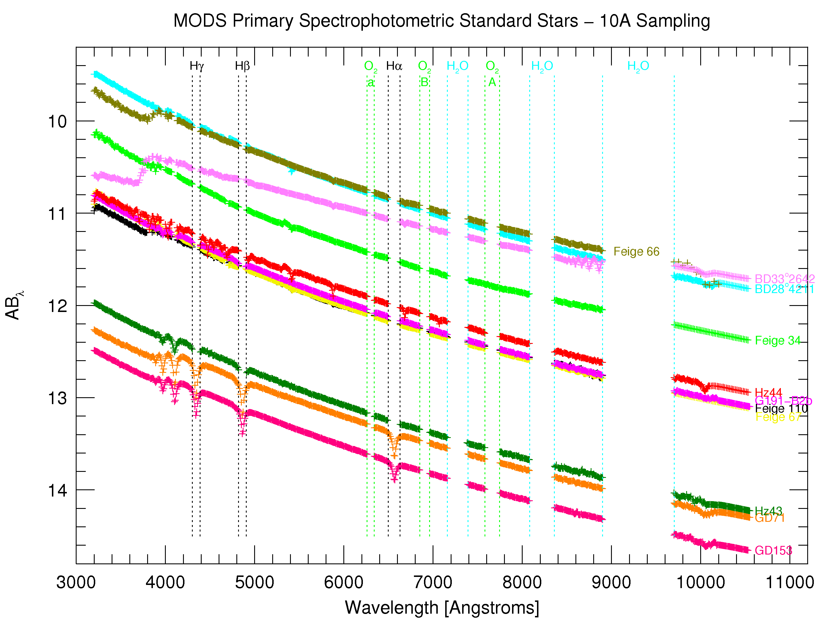
Because MODS works from 3200Å to 10000Å, we need to use standard stars with well-determined fluxes from UV to Near-IR. This section describes our preferred set of standard stars, an approximate model atmospheric extinction curve, standard star observing scripts, and our recommended spectrophotometric calibration strategy.
For each primary standard star we provide flux tables with 10Å sampling. These tables are in IRAF-style ASCII 3-column format ready to be used with IRAF. Where necessary, we used HST stellar models or other HST calibration data to extend the near-IR wavelength coverage to 10500Å. These are suitable for grating-mode calibrations. Wavelengths are vacuum wavelengths as in the original CALSPEC source tables.
We also provide 50Å-sampling flux tables suitable for prism-mode calibrations based on CALSPEC and the Spec50 flux tables (Massey et al. 1988 ApJ, 328, 315) with the Massey & Gronwall (1990 ApJ, 358, 344; M&G90). 50Å tables are not yet available for all primary standards, but will be added as we find suitable data sources.
These tables have the major telluric absorption complexes censored, and we have cut out the brighter stellar absorption lines in most (but not all) tables. This regrettably crowded plot graphically summarizes the primary standard flux table contents. All of these stars are roughly the same color except the redder BD+33°2642, and span about 3 magnitudes in apparent brightness.
The original, uncensored flux tables are available from the HST CALSPEC database.
Note that the modsIDL Reduction Pipeline uses the full CALSPEC flux tables which are included in the software distribution.
| Star | RA | Dec | Sp Type | m(5556) | pmRA | pmDec | t(Grating) | t(Prism) | Downloads |
|---|---|---|---|---|---|---|---|---|---|
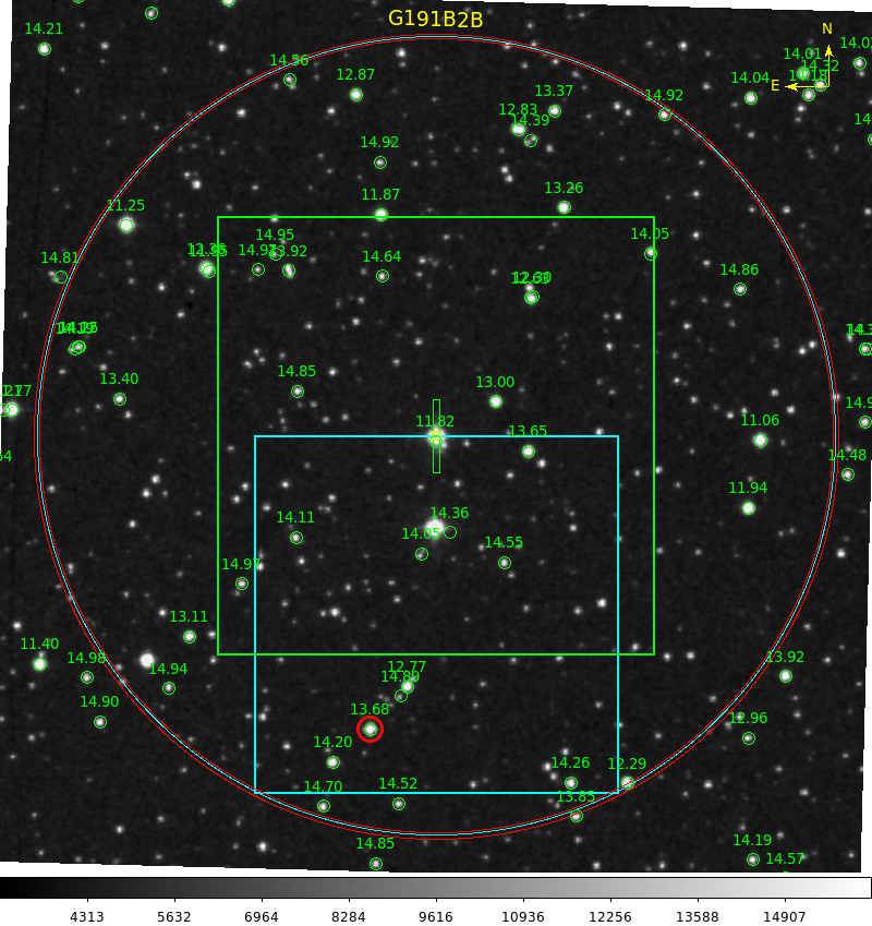
| G191-B2B [1] | 05:05:30.613 | +52:49:51.96 | DA0 | 11.85 | +7.45 | -89.54 | 90 | 10 | Finder Chart Acq Script | Obs Script 10Å Flux Table 50Å Flux Table |
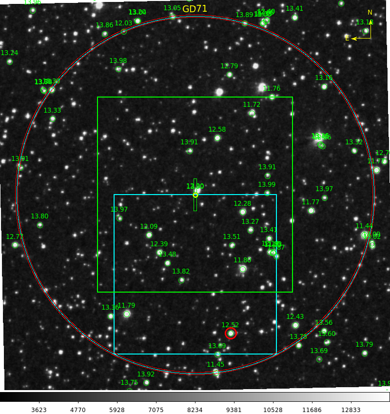
| GD 71 [2] | 05:52:27.614 | +15:53:13.75 | DA1 | 13.03 | +85 | -174 | 180 | 30 | Finder Chart Acq Script | Obs Script 10Å Flux Table 50Å Flux Table |
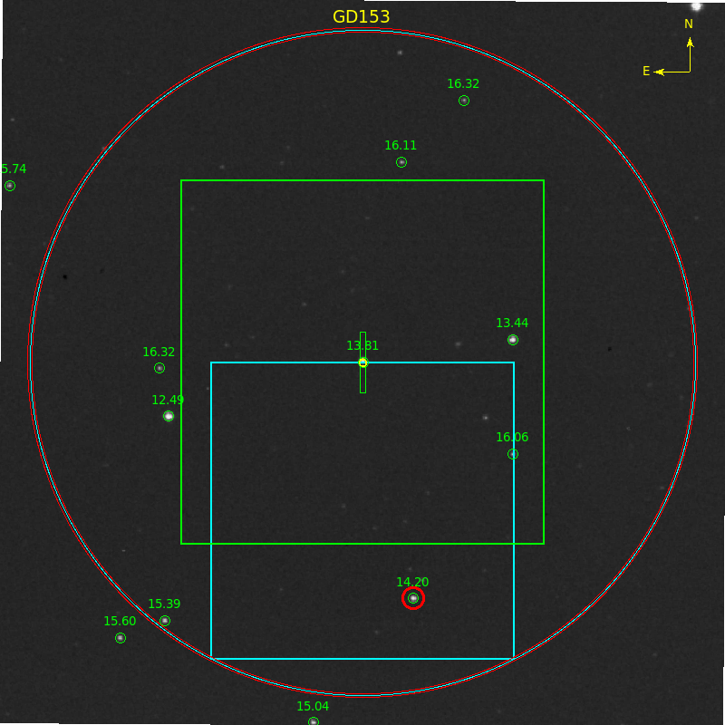
| GD 153 [3] | 12:57:02.337 | +22:01:52:68 | DA1 | 13.35 | -46 | -204 | 180 | 30 | Finder Chart Acq Script | Obs Script 10Å Flux Table |
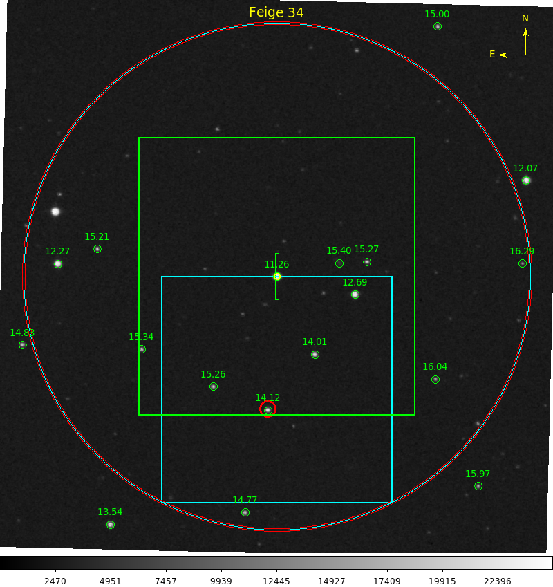
| Feige 34 | 10:39:36.740 | +43:06:09.26 | sdO | 11.25 | +14.09 | -25.01 | 120 | 15 | Finder Chart Acq Script | Obs Script 10Å Flux Table 50Å Flux Table |
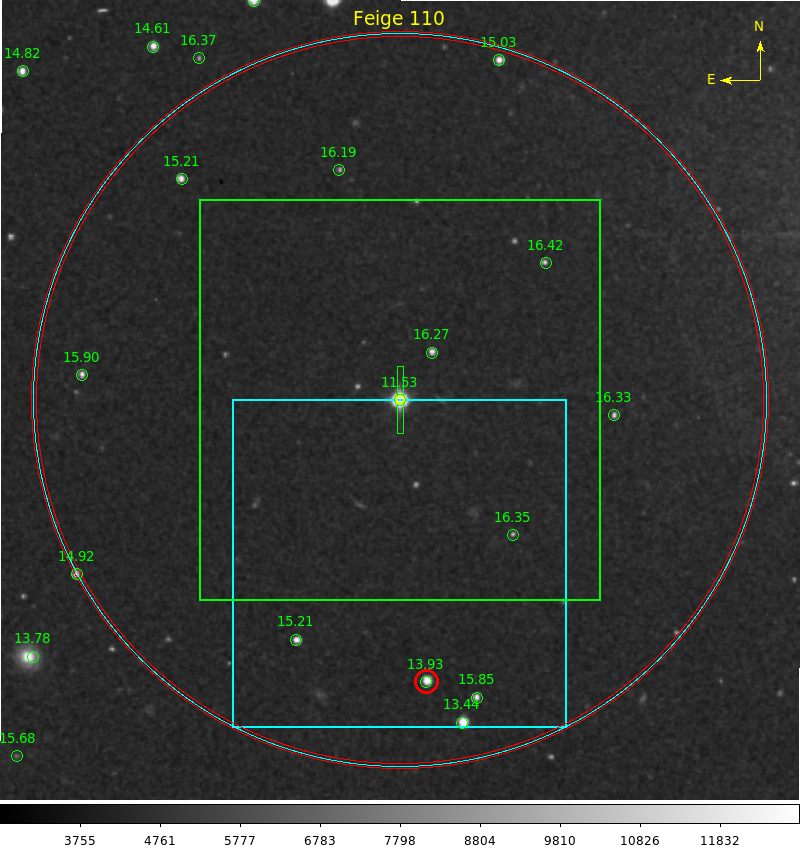
| Feige 110 | 23:19:58.398 | -05:09:56.16 | sdO | 11.88 | -10.68 | +0.31 | 90 | 10 | Finder Chart Acq Script | Obs Script 10Å Flux Table 50Å Flux Table |
| J2000 | J2000 | mag | mas/yr | mas/yr | sec | sec |
We are in the process of compiling a library of MODS spectra taken in all modes of the instrument which will be available online with the recommended flux tables as we progress with reducing the data and verifying the flux tables.
Therefore, as of May 2014 we are withdrawing these standard stars from our recommended list, and removing them from the default calibration program at LBTO.
Legacy copies of the flux tables are available
As an interim measure until we can either obtain a good empirical extinction curve for Mt. Graham or generate an atmospheric model for the site, we have created an approximate extinction curve for Mt. Graham using the well-measured KPNO and Paranal extinction curves scaled to an elevation of 3200-m assuming an atmospheric scale-height of 7000-m and combined. This curve is available for download as an IRAF-style ASCII table:
For applications that only require a good response curve, we recommend
using standard stars observed with the 5-arcsec spectrophotometric
slit mask (LS60x5). This will provide spectra across the
full wavelength coverage with minimal losses due to atmospheric
dispersion and seeing. Note that resolution in the 5-arcsec slit will
be seeing-dependent, but given that the flux calibrations are
typically in 10-50Å bins, this will have little impact on the
derived response curves.
Standards taken through the long-slit masks are recommended only if you also want to use the standard-star spectra to correct for telluric absorption and are willing to accept some atmospheric dispersion losses at the far blue end. Many of the standard stars are in sparse fields that do not always have convenient guide stars for all position angles. This is not as critical as at near-IR wavelengths (e.g., with LUCI), but is an option.